CAUTION:
To safeguard against the potential source of danger which can occur in bladder accumulators, we would like you to pay special attention to the following instructions. Always wear safety shoes, goggles, gloves, and other necessary safety protections during accumulator maintenance.
Bottom Repairable Bladder Accumulators
Item Description
1 Shell
2 Bladder
3 Jam Nut
4 Anti-extrusion Ring
5 Fluid Port
6 Metal Ring
7 O-ring
8 Back-up Ring
9 Gas Valve
10 Spacer
11 Lock Nut
12 Gas Valve Guard
Bladder Repair Kit Consists of:
(2, 6,7,8,9)
Disassembly:
WARNING!
Hydraulic accumulator are pressurized vessels and only qualified technicians should perform the repairs. Never weld, braze or perform any type of mechanical work on the accumulator shell. Always drain the fluid completely from the accumulator before performing any work.
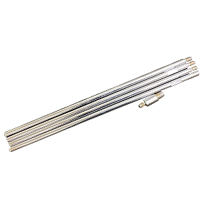
After the accumulator is removed from the equipment, it must be completely depressurized before work is carried out. Take off the gas end valve guard, loose the valve core inside the gas valve slowly using valve ore wrench (included in our accumulator service kit RMK-100). DO NOT take out the valve core quickly under high pressure. Wait until the all the gas comes out.
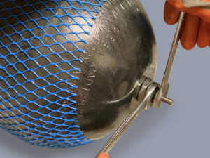
A- Secure the accumulator on the table, remove the bleed plug. Using a spanner wrench (included in our accumulator service kit RMK-100), remove the lock nut and spacer from the fluid port.
B- Push the fluid port inside the shell, remove the anti-extrusion ring and seals. Take out the fluid port.
C- Loose and remove the gas end jam nut from the bladder stem. Push the bladder stem inside the shell. Remove the bladder from the shell.
Pressurized Vessel Use Dry Nitrogen Only
Min. Charging: 25% of maximum working pressure Max. Charging: 90% of minimum working pressure Check Reasontek accumulator charging instructions
Assembly:
Secure the accumulator on the table. The interior of the shell must be cleaned and free of any contamination or debris.
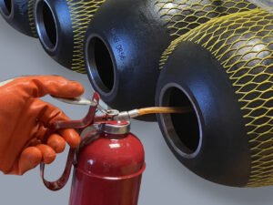
Spray the inside of the accumulator shell with clean system fluid to lubricate the entire shell. Fig.1
Lubricate the bladder. With all gas completely exhausted from the bladder, collapse it, and insert the bladder pull rod on the gas stem. Fig.2
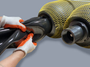
Fold the bladder longitudinally in a compact roll, insert the bladder and pull rod in the shell and through the gas end opening. Push the bladder little by little, do not twist the bladder. Fig.3
Pull the bladder pull rod from the gas end until all the bladder goes in the shell. Install the jam nut on the bladder gas stem. Then install the gas valve on the stem and fasten it with wrenches. Fig.4
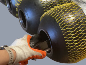
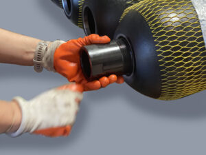
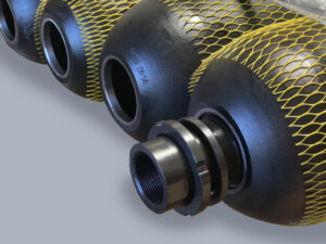
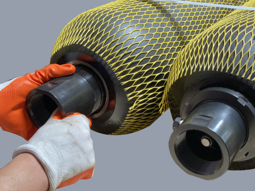
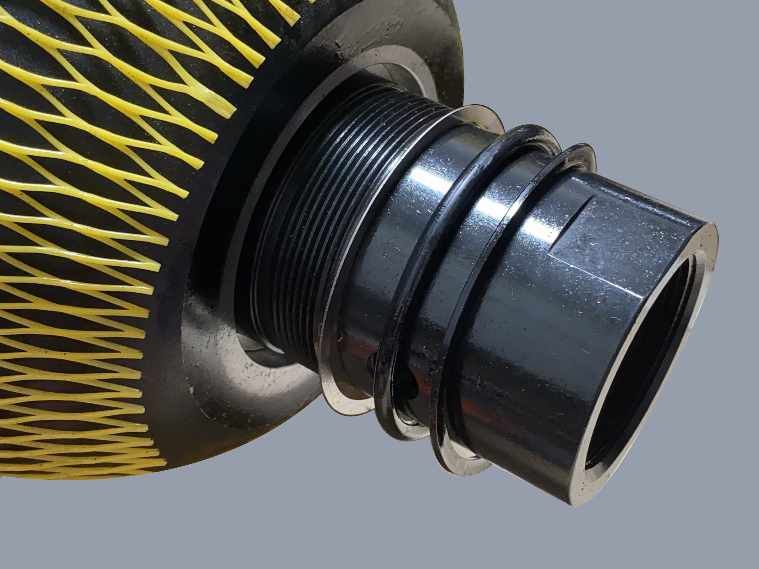
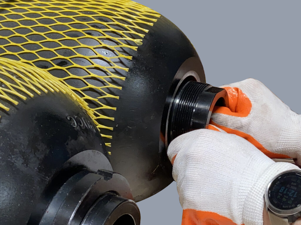
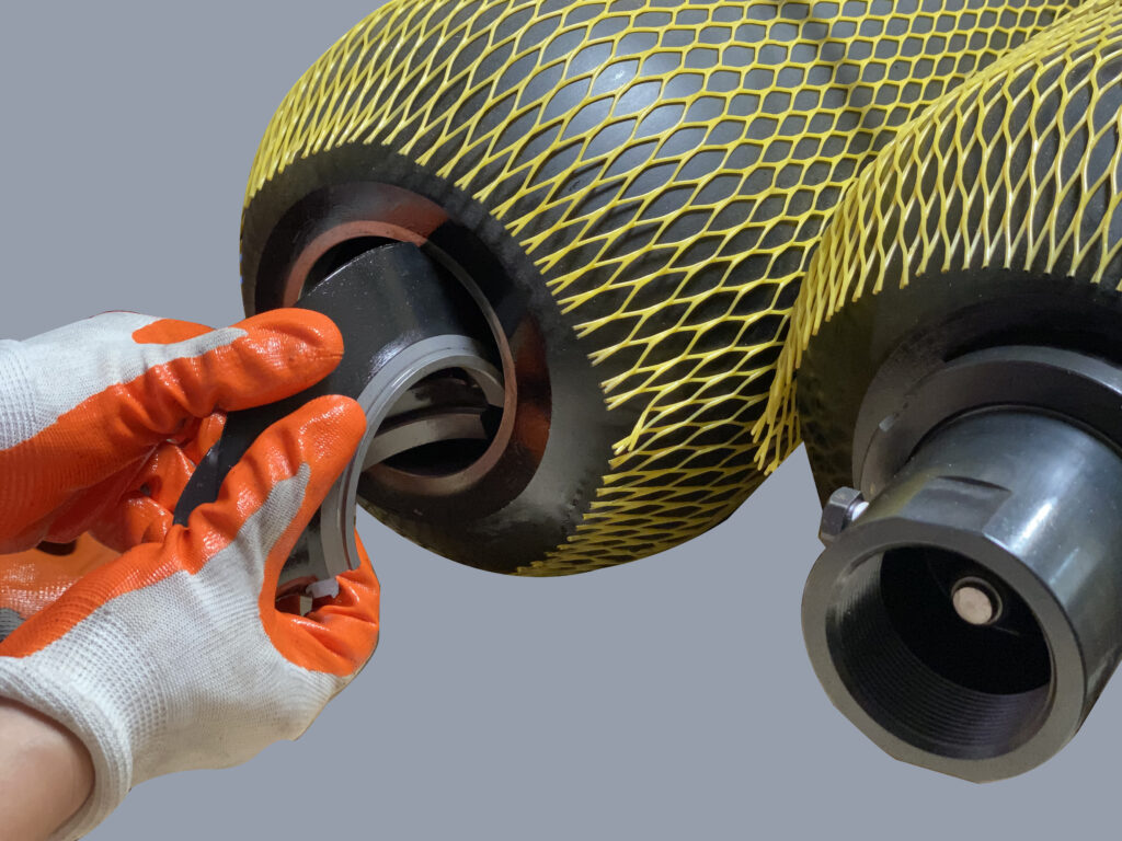
From the fluid end, insert the fluid port (with bleed plug taken off) and anti-extrusion ring into the shell completely. Fig.5
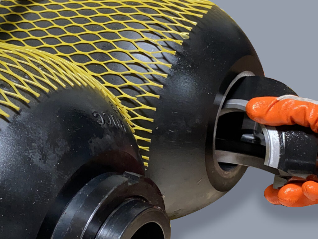
Inside the shell, use hand to take the fluid port out of the shell through the anti-extrusion ring. Make sure the anti-extrusion ring’s metal part faces outside as shown in the above drawing. Fig.6
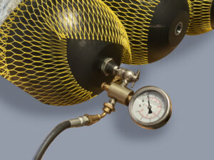
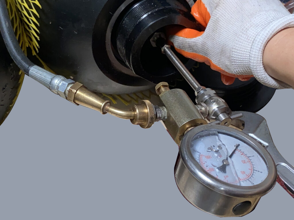
At the gas end, connect the charging kit (model RGA-100-X) to the gas valve. Fig.7
Holding the fluid port straight in position, open the gas cylinder valve to charge the accumulator slowly. Fig.8
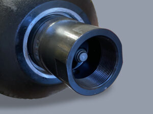
During the pressure charging, bladder expands. The poppet valve inside the fluid port presses the spring and extends out. Fig.9(! Do not watch inside the fluid port directly or very closely during charging, this can be very dangerous if bladder charging failure happens.)
Stop the pressure charging when the pressure gauge reaches 20psi. Disconnect the charging kit. (Check our website for bladder charging instructions using RGA-100-X)
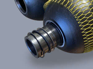
Install the seals at the fluid end by the following order: metal ring first, then the O-ring and back-up ring. Fig.10
Use blunt tool to push the seals inside the fluid port. Make sure the O-ring and back-up ring installed are smooth, flat, and evenly distributed with no twist or curl. Check with light if necessary. Fig.11.
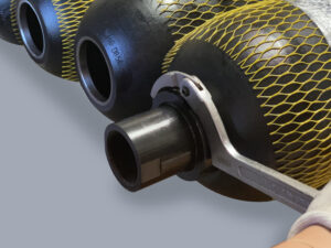
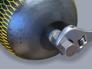
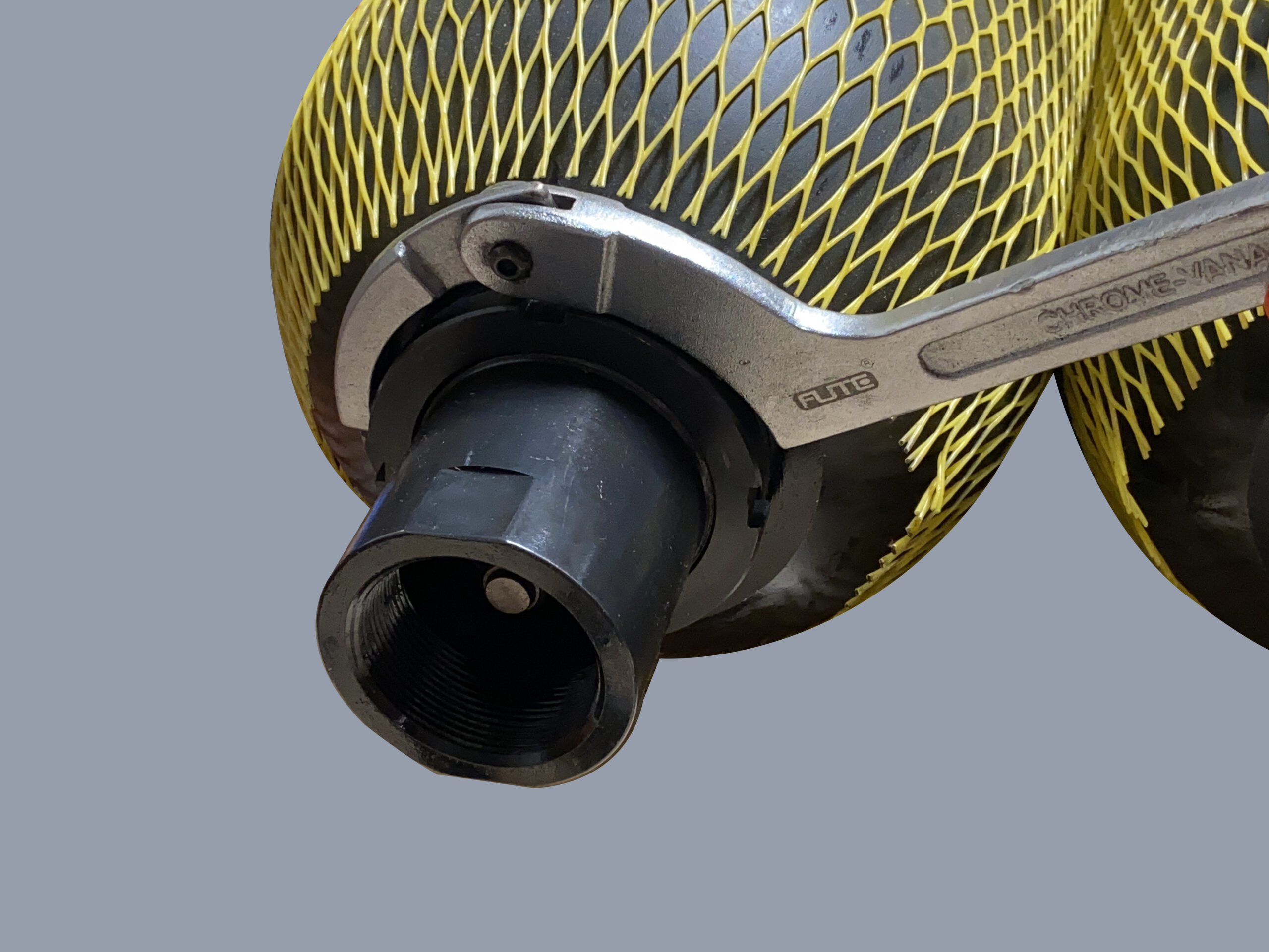
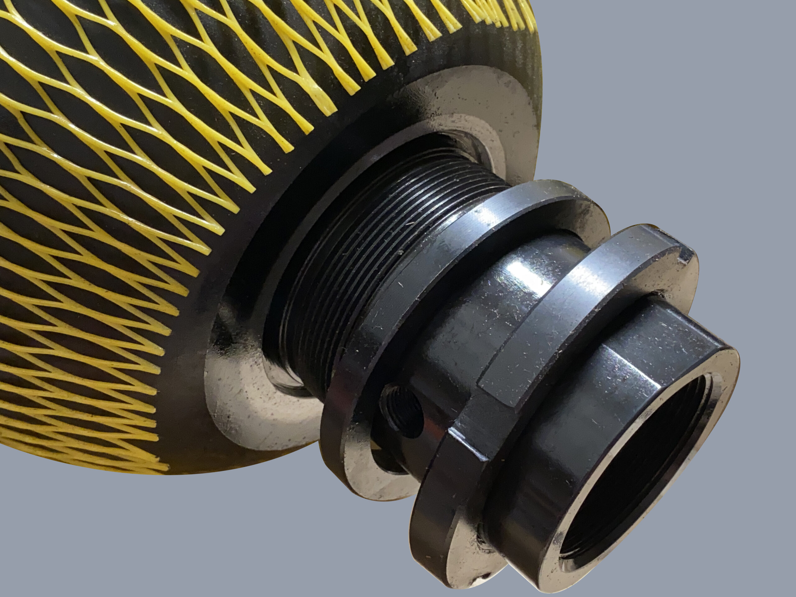
Install the spacer and lock nut (spacer’s lip side facing the shell). Use spanner wrench to tighten the locknut. Fig.12 & Fig.13
Install the bleed plug on the fluid port.
Install the gas valve guard at gas end. Fig.14
Fig.1
Fig.3
Fig.5
Fig.7
Fig.9
Fig.11
Fig.13
Fig.2
Fig.4
Fig.6
Fig.8
Fig.10
Fig.12
Fig.14
Top Repairable Bladder Accumulators
Item Description
1 Shell 2 Bladder 3 Jam Nut 4 Anti-extrusion Ring 5 Fluid Port 6 Metal Ring 7 O-ring 8 Back-up Ring 9 Gas Valve 10 Spacer 11 Lock Nut 12 Gas Valve Guard 13 Top Adapter
Bladder Repair Kit Consists of: (2, 6,7,8,9)
Disassembly:
Follow the disassembly instructions for bottom repairable accumulators above to remove the accumulator from the equipment and depressurize completely.
A- Secure the accumulator on the table, remove the bleed plug. Using a spanner wrench (included in our accumulator service kit RMK-100), remove the lock nut and spacer from the top adapter.
B- Remove the gas valve guard and jam nut from the bladder stem.
C- Push the top adapter with bladder inside the shell. Separate the anti-extrusion ring from the top adapter.
D- Take out the anti-extrusion ring, top adapter, and seals from the shell.
E- Remove the bladder from the shell.
Assembly:
Secure the accumulator on the table. The interior of the shell must be cleaned and free of any contamination or debris.
Spray the inside of the accumulator shell with clean system fluid to lubricate the entire shell.
Lubricate the bladder. Install the top adapter through the bladder stem. Install the jam nut on the stem, use wrench to fasten it. Fig.1
Fold the bladder longitudinally in a compact roll, insert the bladder in the shell at the fluid end towards the other side. Fig.2
Insert the anti-extrusion ring at the gas end. Take the top adapter out of the shell through the anti-extrusion ring. Fig.3 & Fig.4
Insert the gas valve on the bladder stem, use wrench to fasten it. Fig.5
From the fluid end, insert the fluid port and anti-extrusion ring to the shell completely into the shell. Fig.6
Take the fluid port out of the shell through the anti-extrusion ring. Make sure the anti-extrusion ring’s metal part faces outside as shown in the above drawing. Fig.7
Connect the charging kit to the gas valve, using charging valve extension. Fig.8
Holding both top adapter and fluid port straight in position, open the gas cylinder valve to charge the bladder slowly. See the charging section above for bottom bladder accumulators (steps 8,9,10).
Stop the pressure charge when the pressure gauge reaches 20psi. Disconnect and take off the charging kit.
Install the seals on both top adapter and fluid port by the order: metal ring, O-ring, and back-up ring. See the seals installation instructions above for bottom bladder accumulators (steps 11,12). Fig.9
Install the spacer and lock nut for both top adapter and fluid port (spacer lip side facing the shell). Use spanner wrench to tighten. Fig.10 & Fig.11