Accumulators can be used in many different applications, which are related to different equations for calculation. Accumulator calculations are based on the principle of thermodynamic laws:
P1V1=P2V2,Isothermal Condition(Temperature is constant, heat transfer occurs. This is normally for a slow change of gas volume); or,
P1V11.4=P2V21.4, Adiabatic Condition for Nitrogen(no heat transfer. This is for a rapid change of gas volume and temperature changes).
We are giving the calculations below for the most popular applications.
AUXILIARY POWER SOURCE
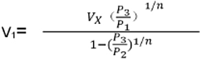
This is also the most common application of hydraulic accumulators. In this application, the accumulator stores the hydraulic fluid delivered by the pump during a portion of the work cycle; then releases this stored fluid upon demand to complete the cycle, functioning as a secondary source of power and assisting the pump by reducing the size of hydraulic power unit.
V1=size of the accumulator required in cubic inches;
P1=Accumulator pre-charged pressure (psi);
P2=System maximum operating pressure (psi);
P3=System minimum pressure (psi);
VX=Volume of fluid required (in3);
N=constant 1.4 for Nitrogen
Isothermal Calculation: select if gas volume changes slowly, while temperature reamins constant. Adiabatic Calculation: select if gas volume changes rapiadly, while temperature changes.
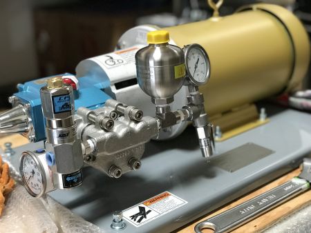
PUMP PULSATIONS DAMPENER
One of the major industrial applications of accumulators is the elimination or reduction of high pressure pulsations generated by the starting pump.
A=Area (square inches) of pump cylinder bore;
K=Constant for particular type of pump (see the table below);
L=Length of piston stroke (in); (or AL=pump displacement in3);
P1=Minimum system pressure or accumulator pre-charge pressure (psi);
P2=System mean pressure (psi);
P3=Maximum system pressure (psi);
N=Constant 1.4 for Nitrogen
Pulsation dampener calculation is typically for piston type pumps, it may not be used for other types of pump.
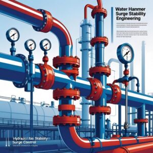
HYDRAULIC LINE SHOCK DAMPENER
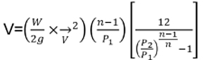
Another major application of accumulator as surge control device is in the suppression or reduction of repeated high pressure pulsations or hydraulic line shock, or so-called “Water- Hammer”. This is caused by the sudden stoppage or deceleration of fluid flowing at high velocity in a pipe line. The rapid pressure or high pressure pulsations or surges produced in the system may cause pump line failure, breaks in the lines, external leakage and severe damage to valves and instruments.
W=Total weight (lbs) of fluid in the pipe line, this is to be calculated by the given pipe I.D, pipe length and fluid density;
v2=Flow Rate Q (GPM)/Pipe flow area A (in2);
P1=System normal pressure (psi)
P2=System maxium allowable shock pressure (psi);
n=Constant 1.4 for Nitrogen
If the system has different pipelines, calculate each horizontal pipeline individually using the tool and sum the results together.
WATER HAMMER VALVE CLOSING TIME
Water hammer is a common harmful phenomenon for pipelines. It is caused mainly by closing the control valve in the sytem to create the pressure surge or shock wave.
Our PulseKushon surge surpressors are specially designed for the pipeline water hammer preventions that are widely used in airport, wate & fuel system, refinery, etc.
Closing the control valves slowly can help alleviate the water hammer problem. In such case, the valve’s critical closing time for water hammer is calculated. In operation, close the valves slower (with longer time) than it’s critical closing time to prevent water hammer and protect the fittings, devices and parts in the system.
Read our technical article of water hammer and solutions in detail.